Coating Width Optimization: Edge Bead Reduction, Trim Waste Minimization, and Slitting Integration
Coating width optimization is a cost-benefit exercise. The final product has a specified width; the coating line must produce a coated web that is at least as wide as that, but any extra width beyond the product width is trimmed off and discarded (or sometimes recycled). This extra width is called the "coating margin" or "trim allowance." The margin must account for: the edge bead region that must be removed, the web wandering (lateral movement) that could cause the coating to miss the edge, the shrinkage of the substrate during drying, and the alignment tolerances of the slitting knives. A typical margin ranges from 5 to 20 mm per side, depending on the line's precision. The cost of this margin is the adhesive/coating material wasted, plus the cost of the substrate lost to trimming. For expensive coatings (e.g., optical adhesives), even a 2 mm reduction per side can save thousands of dollars per roll. Therefore, optimizing the margin is economically attractive. The first step is to quantify the edge bead width and thickness profile. Using a profilometer or a caliper, measure the coating thickness across the width; the edge bead is defined as the region where thickness exceeds the nominal by, say, 10%. That region must be trimmed. The trim width should be slightly larger than the edge bead width to ensure full removal, with an additional safety margin for web wander. The web wander is measured by an edge position sensor over a long run; the standard deviation of the wander is used to set the statistical margin (e.g., 3-sigma). If the wander is ±1 mm, the margin for wander is 1 mm per side. The drying shrinkage is measured by comparing the wet and dry widths; if the substrate shrinks by 0.5%, the margin must account for that. By summing these components, the minimum required coating width can be calculated. If the current coating width is larger, there is an opportunity for savings.
Edge bead reduction is the primary lever to reduce trim waste. As described earlier, techniques include tapered shims, edge vacuum, air knives, and edge deckles. A quantitative approach: evaluate the edge bead profile for each technique and select the one that gives the smallest bead width while maintaining a stable coating window. For example, a tapered shim might reduce edge bead width from 8 mm to 3 mm, cutting trim waste by 62.5%. However, the taper geometry must be optimized; too sharp a taper can cause flow instability. Empirical testing or CFD simulation can guide the taper length and angle. Edge vacuum is effective but consumes energy and can disturb the web; the vacuum level should be just enough to remove the excess without pulling the web. Air knives use a controlled air jet that blows the edge fluid back into the pool; they are simple and low-cost but can cause splashing. Edge deckles provide a physical barrier, but they must be sealed to prevent leakage; they are popular in hot-melt coating. The chosen solution must be compatible with the fluid (e.g., air knives may dry the fluid at the edge, causing plugging). A systematic comparison of these methods under actual production conditions is recommended; the best method may vary with fluid type and speed.
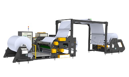
Adhesive coating machine
Integration with slitting is the final step. The coated master roll is taken to a slitting machine where it is cut into multiple narrower rolls. The slitting knives must be positioned so that the trimmed edges are removed and the remaining product rolls are clean and free of edge defects. If the coating margin is too small, the slitter may cut into the edge bead, leaving a thick edge that causes customer complaints (e.g., when the tape is unwound, the edge may lift). If the margin is too large, waste increases. Thus, the slitting width allocation must be coordinated with the
coating width setting. In modern lines, the slitter is often integrated in-line with the coating machine, so the coating width and slitting positions are controlled from the same HMI. Automatic slitter positioning based on the measured coating edge positions is possible with edge sensors feeding data to the slitter controller. This closed-loop system can adjust the slitter knives in real-time to follow the coating edges, allowing a very small margin (e.g., 2 mm per side) without risk of cutting into the bead. This is the "near-zero trim" concept. The economic benefit is significant: for a line producing 10,000 tons of product per year, reducing trim waste from 5% to 2% saves 300 tons of material, which for a $5/kg material equals $1.5 million annually. This justifies the investment in advanced edge detection and automated slitter control.
Practical implementation of width optimization involves several steps: (1) Measure the current coating width profile and edge bead characteristics. (2) Estimate the required components of the margin (bead width, web wander, shrinkage). (3) Calculate the current margin and the potential reduction. (4) Test edge bead reduction techniques on the line with small trial runs, measuring the resulting bead width and coating window. (5) Implement the chosen technique and recalibrate the margin. (6) Integrate the slitter with edge sensors, and set up the control logic. (7) Monitor the trim waste and the product quality (edge integrity) for a validation period. If the margin is reduced too much, occasional defective edges may occur; set the margin to a level where the defect rate is acceptable (e.g., <0.1%). The optimization is not a one-time exercise; it should be reviewed periodically, especially when the substrate supplier changes, the fluid formulation changes, or the line undergoes maintenance that affects alignment. Also, the cost of the coating material vs. the cost of the substrate influences the optimal margin; if the coating is expensive, a smaller margin is preferred even if it requires more precise control. Some plants use an economic model that inputs material prices, line speed, and trim width to calculate the cost per square meter, and then use an optimizer to find the minimum cost point. This model-driven approach ensures that the coating width is always set to the most economical value, balancing quality and waste. In summary, coating width optimization is a multi-faceted engineering task that combines process physics, control technology, and economic analysis. When executed well, it significantly reduces material cost and enhances the competitiveness of the coating operation.